

Demystifying Electro Motive Force (EMF) and Potential Difference
What is Electro-Motive Force (EMF)?
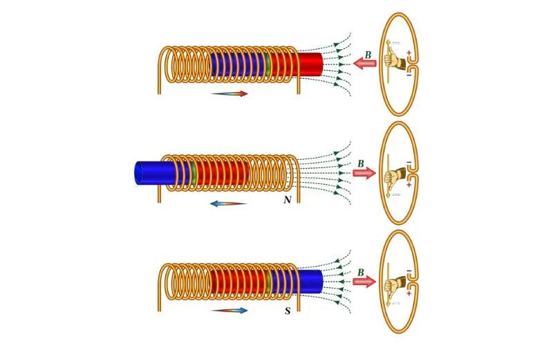
Electro-motive force, often called EMF, is a fundamental concept in electricity and electronics. It represents the electrical potential difference between two points in a circuit when no current is flowing. EMF is responsible for the force that pushes electrons through a conductor, creating an electric current.
The SI unit of EMF
The SI unit of EMF is the volt, represented by the symbol ‘V.’ It is named after Alessandro Volta, an Italian physicist who contributed significantly to understanding electricity. One volt is the EMF that produces a current of one ampere when applied to a one-ohm resistor.
EMF in batteries and generators
EMF is prominently observed in batteries and generators. In a battery, chemical reactions generate EMF, causing electrons to flow through an external circuit, powering various devices. On the other hand, generators use mechanical energy to induce EMF, converting it into electrical energy.
The EMF is the force that sources the current flow in the given circuit and allows us to perceive it, which means a lot of clarity.
Through an easy cell shown in Fig. Owed to the chemical reaction in the solution, terminal ‘A’ has attained a positive charge, whereas terminal ‘B’ has attained a negative charge.
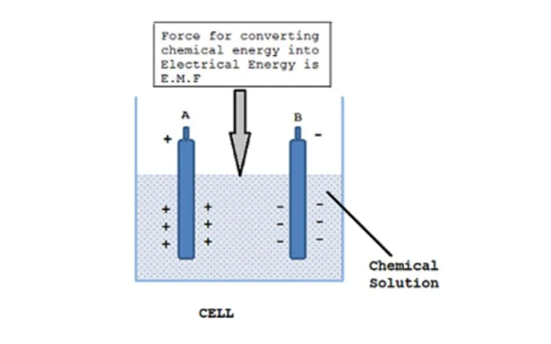
Now, a bit of conductor is joined amongst the terminals A and B, and then the drift of electrons starts through it. This can be nothing, however, the movement of current through the conductor. This can also be shown in the Fig. The electrons can drift from terminal B to A. Hence, the current path is from A to B, i.e., positive to negative.
One might suppose that after the positive charge on terminal A gets neutral due to the electrons, the flow of electrons can stop. Each of the terminals might get neutral once some time. However, this will not happen much. This can result from a chemical change in the solution, maintaining terminal A as charged and terminal B as negatively charged. This keeps the current drift; the chemical change converts chemical energy into electrical energy that supports the flow of electrons.
Consider 2 points P and Q as shown within Fig-b; then this flows from point P to Q. This suggests a potential difference exists between P and Q. This potential difference is termed voltage, denoted as V, and measured in volts.

Understanding Potential Difference (PD)
Potential Difference, called PD or voltage, is the difference in electric potential energy per unit charge between two points in an electrical circuit. The driving force moves electrons through a conductor, creating an electric current.
SI unit of PD
The SI unit of potential difference is also the volt (V), the same as EMF. This common unit underscores the close relationship between EMF and PD in electrical circuits.
PD in electrical circuits
In electrical circuits, a potential difference exists between various points, typically between a power source’s positive and negative terminals, such as a battery. This difference in voltage drives the flow of electrons from high potential (positive terminal) to low potential (negative terminal) through the circuit.

Differences Between EMF and PD
Here’s a table summarizing the differences between Electro Motive Force (EMF) and Potential Difference (PD):
| Aspect of Comparison | Electro-Motive Force (EMF) | Potential Difference (PD) |
|---|---|---|
| Nature of the Concepts | Represents total potential energy in a source when no current is flowing. | The difference in potential energy between two points in a circuit when a current is flowing. |
| Direction of the Force | It always pushes electrons from the negative terminal to the positive terminal of a source. | Depending on the specific connections, it can vary in direction within a circuit. |
| Application in Circuits | Associated with the source of electrical energy, initiates electron flow. | Observed within the circuit, maintains and regulates electron flow. |
This table concisely compares the key differences between EMF and PD, making understanding their distinct roles in electrical circuits easier.
Conclusion
Electro-Motive Force (EMF) and Potential Difference (PD) are fundamental concepts in electricity and electronics. EMF initiates the flow of electrons, while PD ensures their continuous movement through electrical circuits. Understanding these concepts is essential for designing, operating, and maintaining safe and efficient electrical systems in our modern world. Whether it’s the batteries in our devices, the generators in power plants, or the circuits in our homes, EMF and PD are at the heart of it all, making them indispensable concepts for anyone working with electricity.
FAQs
What is the relationship between EMF and voltage?
EMF and voltage are often used interchangeably in everyday language, but they have distinct meanings in physics. EMF represents the total potential difference provided by a source, while voltage (or PD) refers to the potential difference between two points in a circuit. In summary, voltage is a type of potential difference, and EMF is a specific form.
Can PD exist without EMF in a circuit?
No, PD cannot exist without EMF in a circuit. EMF is required to establish the initial potential difference between two points in the circuit. PD is a result of this EMF, which drives the flow of electrons through the circuit.
How do EMF and PD impact electrical safety?
EMF and PD are crucial considerations for electrical safety. They determine the strength of the electrical force within a circuit, which, if not properly managed, can lead to electrical shocks, fires, or damage to electrical equipment. Ensuring that circuits are designed and operated with the right EMF and PD values is essential for maintaining safety.
Can EMF or PD be negative?
Yes, both EMF and PD can be negative. A negative EMF or PD indicates that the potential at one point in a circuit is lower than at another point. This can occur when a circuit is connected in a way that causes the flow of electrons in the opposite direction, or when certain components introduce a voltage drop. Negative values are essential to accurately represent the behavior of circuits in various scenarios.
